
 Beck’s Toolbox
 Knives
 DIY Build Kits
 Digital Downloads
 Machine Accessories
 Fabricating Materials
CNC Machining
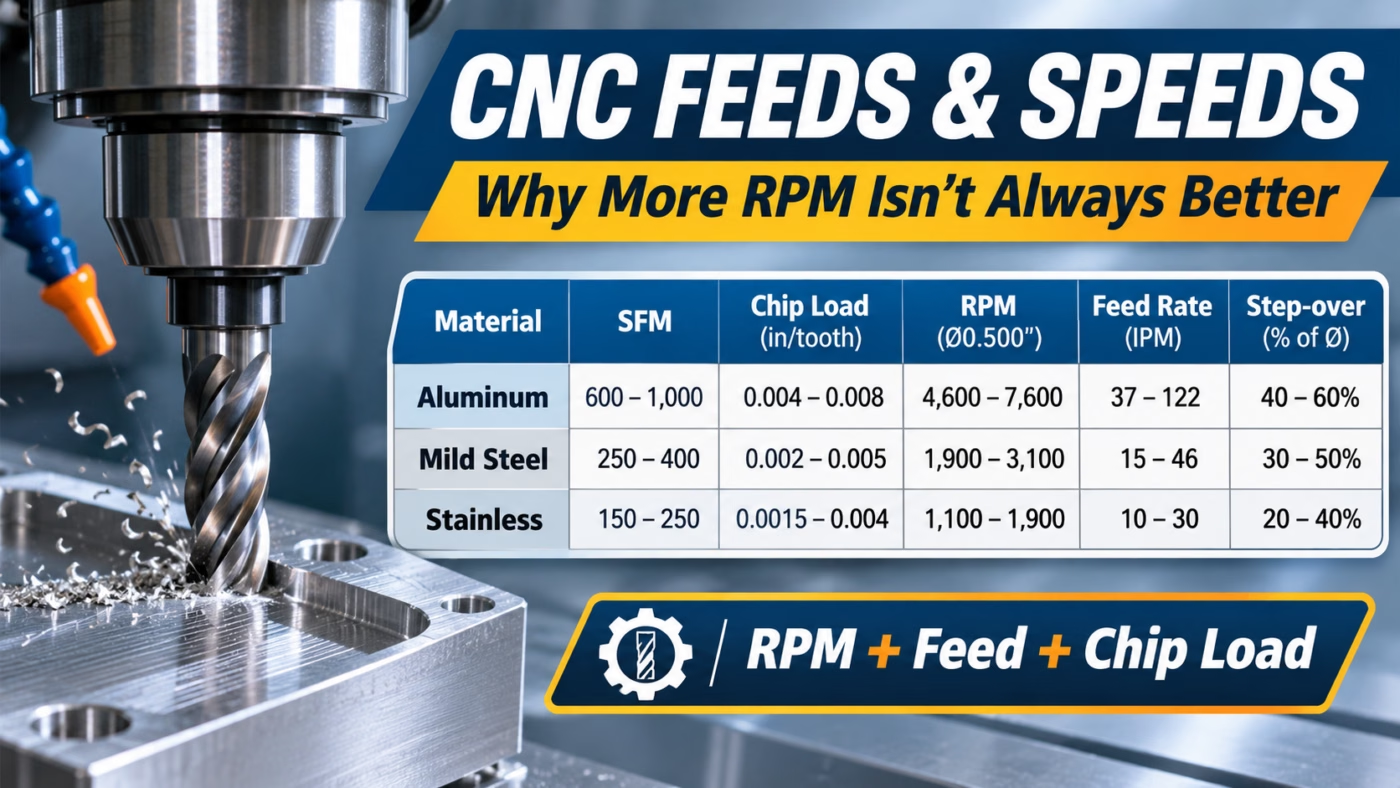
CNC Feeds and Speeds: Why More RPM Isn’t Always Better
Nov
CNC Feeds and Speeds: Why More RPM Isn’t Always Better
Feeds and speeds are probably responsible for more bad CNC advice than almost any other machining topic.
You will hear things like:
“Turn the RPM up until it sounds good.”
“Slow the feed down if the cutter is struggling.”
“More RPM gives you a better finish.”
Sometimes those changes help.
Sometimes they are exactly the wrong thing to do.
The problem is that spindle speed and feed rate are not independent settings. They work together to determine how the cutting edge actually interacts with the material.
Understanding CNC feeds and speeds starts with understanding four different things:
Cutting speed, RPM, feed rate, and chip load.
Once those make sense, a lot of machining behavior becomes much easier to understand.
RPM Is Not the Same Thing as Cutting Speed
RPM simply tells you how many times the cutting tool rotates every minute.
That number by itself tells you almost nothing about the actual cutting conditions.
A 1/8-inch end mill running at 5,000 RPM and a 1-inch end mill running at 5,000 RPM have dramatically different cutting-edge speeds.
The larger cutter travels much farther around its circumference during every revolution.
That is why cutting-tool manufacturers normally specify a recommended surface speed rather than simply giving you an RPM number.
In the United States, this is usually expressed as Surface Feet per Minute, or SFM.
Sandvik Coromant defines cutting speed as the surface speed at which the cutting edge machines the workpiece and calculates spindle RPM from the recommended cutting speed and effective cutter diameter.
Harvey Performance makes the same distinction: cutting speed is based on the material and cutting conditions, while RPM is calculated from that cutting speed and the tool diameter.
That distinction is important.
RPM is the machine setting. SFM describes what is actually happening at the cutting edge.
A Smaller End Mill Needs More RPM
Suppose two carbide end mills are cutting the same material at the same recommended surface speed.
One is 1/2 inch in diameter.
The other is 1/4 inch.
The 1/4-inch tool needs roughly twice the RPM to create the same surface speed at its cutting edge.
That is why simply remembering:
“I run steel at 3,000 RPM.”
is not a useful machining rule.
Change the cutter diameter and the appropriate RPM changes with it.
This is also why high-RPM spindles become especially useful with small cutting tools.
Feed Rate Is Tied Directly to RPM
Now we get to the other half of the equation.
The CNC machine’s feed rate tells you how quickly the cutter moves through the material.
In milling, the feed rate is closely tied to:
- RPM
- Number of cutting edges
- Feed per tooth
Sandvik Coromant expresses that relationship as:
Feed rate = feed per tooth × RPM × number of effective cutting edges.
That means if you increase RPM while leaving your feed rate unchanged, you have changed the amount of material each tooth removes.
You did not simply “speed up the cutter.”
You changed the cutting process.
Chip Load Is What Each Cutting Edge Actually Does
Chip load is commonly expressed as inches per tooth, or IPT.
It represents the programmed advance associated with each cutting edge as the tool rotates.
Imagine a four-flute end mill.
During one revolution, four cutting edges pass through the material.
The machine has to move forward enough during that revolution for each flute to actually remove an appropriate amount of material.
Harvey Performance points out that a chip load that is too large can cause poor chip evacuation and tool breakage, while a chip load that is too small can cause rubbing, chatter, deflection, and poor cutting action.
That second part is where a lot of machinists get into trouble.
Slowing the Feed Can Actually Make Things Worse
Imagine an end mill starts sounding unhappy.
The natural reaction may be:
“I’ll slow the feed down.”
That reduces the load on the machine.
But it also reduces the amount of material each flute removes.
Go far enough and the cutting edge stops forming a healthy chip and starts rubbing across the surface.
Rubbing generates heat.
Now the cutter may get hotter even though you thought you were being easier on it.
The correct response depends on why the cut is unhappy.
Maybe the feed really is too aggressive.
But the problem could also be:
- Too much radial engagement
- Too much axial depth
- Excessive tool stickout
- Poor workholding
- Incorrect SFM
- Poor chip evacuation
- Chatter
Changing feed rate without understanding the cause can simply trade one problem for another.
More RPM Is Not Automatically Better Either
Increasing RPM increases cutting speed.
That generally increases heat generation at the cutting edge.
Every cutting-tool material and coating has an operating range where it performs well.
Run too slowly and you may sacrifice productivity or promote poor cutting behavior.
Run too fast and heat can accelerate wear or damage the cutting edge.
This is why cutting-tool manufacturers publish recommended cutting speeds for specific combinations of tool, coating, and workpiece material.
There is no universal “good RPM.”
Flute Count Changes the Required Feed Rate
Suppose two cutters are running at exactly the same RPM and the same chip load.
One has two flutes.
The other has four.
The four-flute cutter has twice as many cutting edges passing through the material every revolution.
To maintain the same chip load per tooth, the four-flute cutter needs twice the table feed.
This is one reason you cannot swap a two-flute and four-flute end mill and automatically leave everything else unchanged.
The flute count is part of the feed calculation.
Of course, flute count also affects chip space, tool strength, and material suitability.
A high-flute-count cutter may work extremely well in steel while creating chip-evacuation problems in an aggressive aluminum cut.
Tool geometry and feeds and speeds have to be considered together.
Radial Engagement Changes the Real Chip Thickness
This is where feeds and speeds get more interesting.
Feed per tooth and actual chip thickness are not always the same thing.
When the radial width of cut drops below approximately half the cutter diameter, radial chip thinning begins to matter.
The actual maximum chip becomes thinner than the programmed feed per tooth would suggest.
Harvey Performance specifically warns that once radial engagement drops below 50% of cutter diameter, maximum chip thickness decreases. If the feed is not adjusted, that can contribute to rubbing, poor finish, inefficient cutting, and premature tool wear.
This is one of the reasons modern high-efficiency toolpaths can run feed rates that look crazy compared with traditional milling.
They use a relatively small radial engagement.
The reduced engagement creates chip thinning, so the programmed feed can be increased while keeping the actual maximum chip thickness appropriate.
This Is Why Adaptive Toolpaths Can Run So Fast
A traditional slotting operation engages a large portion of the cutter.
The tool experiences high cutting forces and has relatively little opportunity to cool between engagements.
A modern adaptive or high-efficiency strategy may use a much smaller radial engagement and a deeper axial cut.
That changes the load on the cutter dramatically.
Because the radial engagement is smaller, you may be able to increase feed substantially while still maintaining the chip thickness the tool was designed to produce.
That does not mean:
“Adaptive toolpaths let you crank the feed up.”
It means the engagement changed, so the correct cutting parameters changed with it.
Depth of Cut Matters Too
You cannot talk about feeds and speeds without considering how much of the cutter is engaged.
A 1/2-inch end mill taking a 0.020-inch radial finishing pass is experiencing a very different load than the same cutter buried in a full-width slot.
Even if RPM and feed rate are identical.
Harvey Performance notes that axial depth of cut and radial depth of cut are important parts of material-removal calculations and that different operations require different running parameters.
This is why a feeds-and-speeds recommendation without a depth-of-cut recommendation is incomplete.
Tool Stickout Changes What You Can Get Away With
Tooling manufacturers can publish cutting data assuming a reasonably rigid setup.
Your machine may not match that setup.
If the cutter is hanging several inches out of the holder, its ability to resist radial cutting forces changes dramatically.
A long tool acts more like a spring.
The cutter can deflect, vibrate, and chatter even though the recommended feeds and speeds are perfectly reasonable for a shorter setup.
This is one reason blindly entering catalog numbers into the CNC control does not guarantee success.
Manufacturer recommendations are a starting point for the complete machining system.
Your Machine Matters Too
A feed and speed combination may be perfectly reasonable for the cutting tool and still be inappropriate for the machine.
Consider:
- Maximum spindle RPM
- Available spindle power
- Low-speed torque
- Machine rigidity
- Toolholder rigidity
- Acceleration capability
- Control processing speed
Small high-performance cutters may want more RPM than an older machine can provide.
A large cutter in steel may require more torque than a small high-speed spindle can deliver.
The cutter, machine, and toolpath all have to work together.
Sound Is Useful, But It Is Not a Measuring Instrument
I absolutely listen to a cut.
Machinists should.
Changes in sound can alert you to:
- Chatter
- Chip recutting
- Tool wear
- Poor engagement
- Instability
But sound should help diagnose the process, not replace cutting data.
A quiet cut is not automatically a good cut.
You can run a carbide end mill extremely gently and quietly while rubbing the cutting edges to death.
Likewise, an aggressive but healthy cut may sound much more violent while producing excellent chips and good tool life.
Look at the complete process.
Chips Tell You a Lot
The chip is the physical evidence of what the cutting edge is doing.
Look at:
- Chip shape
- Chip thickness
- Chip color
- Whether chips are leaving the cut
- Whether material is welding to the cutter
- Whether chips are being recut
If the cutter is creating dust instead of recognizable chips in an operation that should be cutting aggressively, that can be a clue that the tool is rubbing rather than cutting effectively.
If chips are packing into the flutes, the programmed chip load may not be the only problem. You may have inadequate flute space or poor evacuation.
The chip is worth paying attention to.
Use the Tool Manufacturer’s Data First
This is one rule I strongly recommend.
If you bought a specific end mill from a reputable tooling manufacturer, start with the cutting data supplied for that tool.
The manufacturer knows:
- Carbide grade
- Coating
- Flute geometry
- Edge preparation
- Intended application
A generic internet chart does not.
Harvey Performance specifically recommends using manufacturer-provided speeds and feeds data calculated for the particular cutting tool and application.
Sandvik Coromant also provides its milling formulas and recommended cutting-data tools so that spindle speed, feed per tooth, engagement, and actual cutting conditions are treated as connected variables rather than isolated numbers.
For reference, their technical resources are worth bookmarking:
Harvey Performance — Speeds and Feeds 101
Harvey Performance — How to Combat Chip Thinning
Sandvik Coromant — Milling Formulas and Definitions
Feeds and Speeds Affect the Parts We Make Too
These concepts are not just theory.
The CNC-machined aluminum wheels in the Beck Tools Belt Grinder Wheel Kit require controlled machining around bearing locations and running surfaces.
The machined components in the BA Shredder 2×72 Belt Grinder also depend on choosing cutting conditions that produce the dimensions and surfaces the assembly actually needs.
Good feeds and speeds are ultimately about producing a consistent part without unnecessarily sacrificing tooling or cycle time.
A Better Way to Approach a New Cut
When I am setting up an unfamiliar operation, I would rather work through the variables in order than randomly adjust RPM and feed until the machine sounds acceptable:
- Identify the exact tool and workpiece material.
- Start with the tool manufacturer’s recommended cutting data.
- Calculate RPM from the recommended surface speed and cutter diameter.
- Calculate feed from RPM, flute count, and recommended feed per tooth.
- Account for radial and axial engagement.
- Correct for chip thinning when appropriate.
- Make sure the machine, holder, workholding, and tool stickout can support the cut.
- Run the operation and evaluate the chips, sound, finish, spindle load, and tool condition.
Then make controlled adjustments.
Change something because you understand what you are trying to correct.
The Bottom Line
CNC feeds and speeds are not simply two numbers you type into a program.
RPM determines cutting speed.
Feed rate, RPM, and flute count determine programmed feed per tooth.
Radial engagement affects actual chip thickness.
Depth of cut affects cutting forces.
Tool stickout, machine rigidity, workholding, material, coating, and chip evacuation all influence what the cutter can tolerate.
That is why copying somebody else’s RPM and feed rate from the internet can be completely meaningless without knowing their complete setup.
Start with reputable cutting-tool manufacturer data.
Understand what the numbers represent.
Then adjust the process based on what the tool and machine are actually doing.
If you need a custom component, prototype, replacement part, or short production run manufactured, visit our CNC Machining Services page to request a quote.
