
 Beck’s Toolbox
 Knives
 DIY Build Kits
 Digital Downloads
 Machine Accessories
 Fabricating Materials
CNC Plasma Cutting
CNC Plasma Kerf Compensation: How to Cut Accurate Parts
Sep
CNC Plasma Kerf Compensation: Why Your Parts Are the Wrong Size
Have you ever designed a part in CAD, cut it on your CNC plasma table, and discovered that the finished part was slightly smaller than it should have been?
Or maybe you’re cutting a hole for a bolt, only to discover that the bolt won’t fit.
Before blaming your machine’s accuracy, there’s something you should check: kerf compensation.
Kerf compensation is one of the most important settings for producing dimensionally accurate CNC plasma parts. Understanding how it works can eliminate a surprising number of problems.
What Is Kerf in Plasma Cutting?
Kerf is the width of material removed by the plasma arc as it travels through the workpiece.
Unlike a laser or an extremely sharp cutting tool, a plasma arc removes a relatively wide path of material.
That width depends on several factors:
-
Amperage and consumable selection
-
Cutting speed
-
Torch height
-
Material type and thickness
-
Consumable condition
The important thing to understand is that your plasma arc has a measurable width.
If your CNC machine follows the exact geometry of your CAD model without compensating for that width, your finished parts won’t match your drawings.
How Kerf Compensation Works
Imagine designing a 2-inch square in CAD.
If your plasma torch follows the exact perimeter of that square, the arc removes material from both sides of the programmed cutting path.
Part of that material comes from inside your intended finished geometry.
Consequently, your finished part ends up smaller than 2 inches.
Kerf compensation solves this problem by offsetting the torch’s cutting path.
For external profiles, the torch moves slightly outside the finished geometry. For internal profiles, such as holes, the cutting path moves inside the geometry.
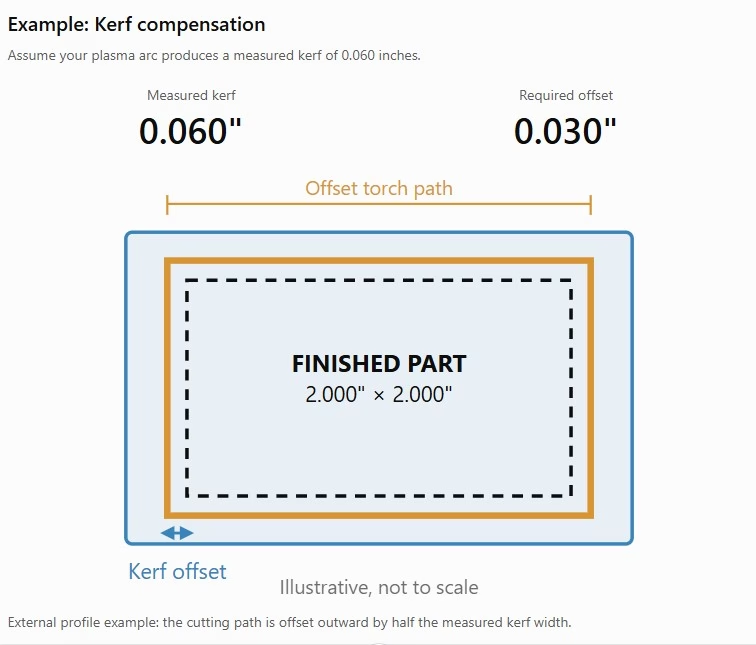
Example: Kerf compensation
Assume your plasma arc produces a measured kerf of 0.060 inches.
Measured kerf
0.060″
Required offset
0.030″
External profile example: the cutting path is offset outward by half the measured kerf width.
Most CNC plasma CAM software allows you to enter the kerf width. The software then calculates the appropriate toolpath offset.
Just make sure you understand whether your software is asking for the full kerf width or the actual offset distance.
Entering the wrong value can double your dimensional error.
How to Measure Your Actual Plasma Kerf
This is where I would start rather than relying entirely on an estimated number.
Your actual kerf can differ from the value listed in your cutting software.
A simple test cut can help establish a much more accurate starting point.
-
Select your material, amperage, consumables, and cutting speed.
-
Draw a reasonably large square in your CAD software.
-
Disable kerf compensation for the test.
-
Cut the square using your normal cutting parameters.
-
Measure the finished part in both directions.
For example, suppose you programmed a 3.000-inch square without kerf compensation, but the finished part measures 2.940 inches.
Assuming the machine is mechanically accurate and the cut is reasonably square, that suggests an approximate kerf width of 0.060 inches.
This works because you’re losing approximately half the kerf width on each side of the part.
For more accurate measurements, you can also cut a straight slot and measure its width. Account for any arc lead-in or lead-out geometry that might distort the measurement.
Once you establish your actual kerf, enter that value into your CAM software and run another test.
Why Holes Require Additional Attention
External profiles are generally more forgiving than small internal features.
Cutting a 12-inch plate to size is relatively straightforward. Cutting a precise 0.250-inch hole is considerably more challenging.
Several things happen when cutting small holes.
First, the machine must maintain accurate circular motion while the plasma arc continues removing material.
Second, lead-ins and lead-outs must fit inside the available scrap area without damaging the finished edge.
Third, the plasma arc isn’t perfectly cylindrical. It can produce taper, particularly when the cutting conditions aren’t optimized.
This is why kerf compensation alone won’t guarantee perfectly sized holes.
For critical holes, I prefer considering whether it makes more sense to plasma cut a smaller pilot hole and finish it with a drill or machining operation.
There’s no reason to demand machining tolerances from a plasma cutter when a secondary operation is quicker and more reliable.
Your Cutting Parameters Affect Kerf Width
One mistake is measuring kerf once and assuming that value applies to every material and cutting condition.
Changing amperage, consumables, material thickness, or cutting speed can change the resulting kerf.
Ideally, you should establish separate cutting profiles for the materials and thicknesses you regularly process.
Each profile should include the appropriate cutting parameters and kerf compensation.
This becomes particularly useful when cutting nested parts because dimensional errors can accumulate into expensive scrap.
Kerf Compensation Won’t Fix Mechanical Problems
Before adjusting your compensation values to correct inaccurate parts, make sure the machine itself is functioning correctly.
If your torch isn’t perpendicular to the material, the resulting bevel can make your dimensional measurements misleading.
Our article on Why CNC Plasma Torch Squareness Matters for Cut Quality explains why proper alignment is important.
Your torch also needs to remain securely positioned throughout the cutting process.
That’s one reason our full-radius CNC plasma torch holder design focuses on securely supporting the machine torch rather than concentrating clamping pressure at a few points.
You should also verify that your torch lead isn’t pulling on the floating Z-axis.
As explained in Why Torch Lead Routing Matters on a CNC Plasma Table, cable tension can change the actual torch position and interfere with cutting accuracy.
If the mechanical setup isn’t correct, adjusting kerf compensation can simply hide one problem while creating another.
A Simple Way to Improve Cutting Accuracy
The process I recommend is straightforward.
Get your cutting parameters dialed in first. Make sure you’re producing clean edges with minimal dross.
Next, verify the machine’s mechanical accuracy and torch alignment.
Once those variables are under control, perform a test cut and establish your actual kerf width.
Enter that value into your cutting software and run another test.
If you regularly process several different materials and thicknesses, create separate cutting profiles rather than repeatedly entering new settings from memory.
Most importantly, don’t use kerf compensation to correct problems caused by incorrect cutting speed, torch height, or mechanical alignment.
The Bottom Line
Kerf compensation is a relatively simple concept that can make a significant difference in CNC plasma cutting accuracy.
However, the correct compensation value depends on your actual cutting conditions.
Measure your kerf, verify your machine, and establish repeatable cutting profiles.
Getting those details right means fewer rejected parts, less wasted material, and significantly less time trying to figure out why your CAD dimensions don’t match your finished parts.
For additional CNC plasma cutting information and practical shop advice, visit the Beck Tools Guides.
